Moving bulk materials efficiently without product degradation, pipeline plugging, or excessive downtime remains a primary operational bottleneck in industrial processing facilities. Relying on generalized equipment specifications rather than empirical material data leads to mismatched conveying methods. This oversight results in severe component wear, high energy consumption, and compromised product integrity. Plant managers and process engineers often face the consequences of poorly specified blowers or incorrect pipe schedules months after commissioning.
This guide breaks down the technical evaluation process for pneumatic conveying system selection. We focus on material characteristics, flow regimes, and system design trade-offs to ensure reliable, long-term bulk material handling. You will learn how to match physical material properties to the correct transport phase, avoiding the common pitfalls of undersized filtration or excessive transport velocities.
Material properties—specifically bulk density, particle shape, abrasiveness, and friability—serve as the non-negotiable baseline for determining the required flow regime.
Dilute phase systems offer lower upfront capital expenditure but incur higher energy consumption and pipeline wear; dense phase systems require higher initial investment but protect fragile materials and reduce maintenance.
Choosing between positive pressure and vacuum conveying is dictated by facility layout, specifically the ratio of material pick-up points to discharge destinations, as well as material toxicity.
Accurate pneumatic conveying system selection requires balancing peak transfer rate requirements with routing complexity, vertical lifts, and available utility air.
Implementation success hinges on empirical material testing, accurate filtration sizing, and mitigating operational risks like line plugging and combustible dust hazards.
Table of Contents
Engineering a reliable material transfer solution begins with quantifying exact production demands and mapping the physical environment. System sizing relies entirely on accurate throughput data and spatial constraints. You cannot design a functional pipeline network based on rough estimates of daily production.
Process engineers must differentiate between average continuous processing rates and peak surge capacities. A facility may require 10,000 pounds of material per hour on average to feed a downstream packaging line. However, if that material is delivered via intermittent bulk bag unloaders that take 15 minutes to switch out, the system must actually convey at a peak rate of 15,000 pounds per hour during active operation to maintain the required average. Failing to account for this surge requirement guarantees the system will fall behind production demands.
Evaluating the impact of batch versus continuous feeding directly influences system sizing and air consumption. Continuous feeding via volumetric or gravimetric feeders provides a steady material stream. This allows for smaller pipe diameters and lower, consistent air volumes. Batch feeding dumps large volumes of material rapidly into pressure vessels. This demands higher instantaneous air volumes and larger pipe schedules to clear the line before the next batch drops. We always recommend continuous feeding where possible to stabilize the air-to-material ratio.
Mapping the physical footprint requires calculating total horizontal runs, vertical lifts, and the number of directional changes. In pneumatic design, elbows create significant resistance. A single 90-degree sweep elbow can add the equivalent of 20 feet of straight pipe resistance to the system calculations. Vertical lifts demand higher transport velocities to overcome gravity and prevent material fallback, known as choking.
To accurately assess routing complexity, follow these field measurement steps:
Measure the exact linear distance from the material pick-up point to the final discharge nozzle.
Count every planned directional change and specify the required degree (e.g., 45-degree, 90-degree).
Calculate the total vertical lift, noting any sections where the pipe must route around existing structural beams or HVAC ductwork.
Identify the available floor space for the prime mover, ensuring adequate clearance for maintenance access and acoustic enclosures.
Verify the structural load capacity of the destination silos to ensure they can support the dynamic weight of filter receivers and the vibration of pulse-jet cleaning cycles.
Assessing available floor space and structural support dictates component placement. Prime movers like positive displacement blowers require sound enclosures and vibration isolation. Filter receivers placed on top of tall silos demand robust structural engineering to handle wind loads. Pressure vessels used in dense phase systems require significant vertical clearance beneath feed hoppers, often necessitating structural modifications to the facility floor.
Material behavior dictates every aspect of pneumatic design. Ignoring physical and chemical properties guarantees system failure, frequent maintenance, or ruined product. You must test the specific material you intend to convey, as even slight variations in moisture or particle size distribution completely alter flow dynamics.
Bulk density dictates the air-to-material ratio and minimum conveying velocities required to keep particles in suspension. Heavier materials demand higher air velocities to prevent saltation—the point where particles drop out of the airstream and settle on the bottom of the pipe. Lighter materials require less air but can be prone to fluidization issues in the feed hopper, causing them to flush uncontrollably through rotary valves.
Particle shape impacts flowability and the risk of bridging or ratholing in hoppers. Spherical particles flow easily and feed consistently into the airstream. Angular or interlocking particles resist flow. They often require mechanical agitation, vibration, or aeration pads in the feed bin to maintain a steady feed rate into the conveying line.
Handling differences between cohesive, interlocking, and highly fluidizable powders require specific feed mechanisms. Cohesive powders like titanium dioxide clump together and coat pipeline walls, eventually choking the system. Highly fluidizable powders like fly ash behave like liquids when aerated. They require specially toleranced rotary valves with vented pockets to prevent air from blowing back into the feed hopper and disrupting the material flow.
Utilizing the Mohs hardness scale helps identify wear risks for pipelines, elbows, and rotary valves. Materials with a Mohs hardness above 4, such as silica sand, alumina, or glass cullet, rapidly erode standard carbon steel components. These applications demand specialized wear-resistant components. We frequently specify ceramic-backed elbows or blind tees for these materials. A blind tee uses a trapped pocket of the material itself to absorb the impact of incoming particles, protecting the metal housing from erosion.
Establishing velocity limits protects fragile, agglomerated, or blended materials from high-impact degradation and separation. Coffee beans, pet food kibble, and spray-dried dairy powders shatter if conveyed at high speeds. High velocities also cause blended materials with varying particle sizes to segregate during transit. The heavier particles drop out of suspension faster than the lighter ones, ruining the homogeneity of the final product by the time it reaches the destination silo.
Hygroscopic materials absorb moisture from the conveying air. Handling sugar, urea, or certain salts requires dry utility air or closed-loop nitrogen purging. If ambient plant air is used, the moisture will cause the material to cake and cement inside the pipeline, requiring complete system disassembly to clear the blockage.
Chemical reactivity and corrosiveness dictate pipeline material selection. Handling corrosive chemicals or food-grade products mandates 304 or 316 stainless steel piping with specific internal surface finishes to prevent bacterial growth. Standard industrial powders typically allow for standard carbon steel or aluminum piping, which reduces material costs significantly.
Evaluating explosion risks associated with combustible dust defines necessary safety compliance measures. Organic dusts, plastics, and metal powders present severe deflagration hazards. System design must incorporate explosion venting, chemical suppression systems, and mechanical isolation valves. These components contain and direct blast pressures safely away from personnel and equipment, ensuring full compliance with NFPA and ATEX regulations.
Selecting the correct flow regime aligns the conveying physics with the material's limitations and the facility's operational goals. This is the most critical phase of pneumatic conveying system selection. Choosing the wrong regime guarantees operational headaches.
Dilute phase conveying operates as a high-velocity, low-pressure suspension flow where particles remain fully airborne. Air velocities typically exceed 3,500 feet per minute, keeping the material dispersed evenly throughout the pipeline cross-section. The air-to-material ratio is high, meaning you are moving a lot of air to transport a relatively small amount of product.
This regime is best for non-abrasive, non-fragile materials like flour, plastic pellets, and grain. It handles short-to-medium transfer distances effectively. The primary trade-offs involve higher component wear and continuous energy use due to the high air volumes required. However, the initial equipment investment remains lower, and the control systems are relatively simple to operate and maintain.
Dense phase conveying utilizes a low-velocity, high-pressure slug or plug flow. Material moves in distinct waves or solid plugs separated by pockets of high-pressure air. Velocities often remain below 1,000 feet per minute. Because the material is not fully suspended, the air-to-material ratio is very low.
This method is best for highly abrasive, friable, or heavy bulk materials, and long-distance routing. The low velocity prevents abrasive particles from destroying elbows and stops fragile particles from shattering against the pipe walls. The trade-offs include a taller equipment footprint to accommodate pressure vessels (blow tanks) and complex air injection controls. These factors are balanced by significantly reduced maintenance interventions and excellent product preservation.
Semi-dense phase conveying operates at an intermediate velocity utilizing a partially aerated flow. The material moves in a turbulent, dune-like pattern along the bottom of the pipe, rather than being fully suspended or moving in solid plugs.
It is best for aeratable materials like cement, fly ash, and mildly abrasive powders. This regime offers a middle ground, balancing air consumption with moderate pipeline wear, making it highly effective for specific mineral and chemical applications where full dense phase is unnecessary but dilute phase would cause too much erosion.
Operational Parameters by Transport Method
Transport Method | Velocity Range | Pressure Range | Ideal Material Types | Primary Advantage |
|---|---|---|---|---|
Dilute Phase | High (>3,500 fpm) | Low (<15 psig) | Non-abrasive, durable, light | Simple controls, lower initial investment |
Semi-Dense Phase | Medium (1,500 - 3,000 fpm) | Medium (15 - 30 psig) | Aeratable, mildly abrasive | Balances air usage and pipeline wear |
Dense Phase | Low (<1,000 fpm) | High (>30 psig) | Highly abrasive, fragile, heavy | Protects material, minimizes pipe erosion |
The physical layout of the process equipment dictates whether the system should push material using positive pressure or pull it using a vacuum. You must evaluate the number of source points versus the number of destination points.
Positive pressure systems introduce compressed air at the beginning of the conveying line to push material toward its destination. This design logic is best suited for applications requiring a single material pick-up point delivering to multiple discharge destinations. A common example is moving plastic resin from a single outdoor bulk storage silo to multiple indoor extruder hoppers.
These systems are capable of pushing materials over longer distances and at higher capacities than vacuum systems because they can utilize higher pressure differentials. A standard positive displacement blower can generate up to 15 psig of push, providing significant motive force to keep heavy materials moving through long horizontal runs.
Vacuum systems utilize an air mover at the end of the line to draw air and material through the piping. This design logic is ideal for drawing material from multiple pick-up points to a single discharge destination. For instance, pulling various minor ingredients from several bulk bag unloaders into a single batching mixer.
Vacuum conveying is inherently cleaner and safer for toxic or highly dusty materials. Because the pipeline operates under negative pressure, any leaks in the piping network will draw ambient air inward. This prevents hazardous dust from blowing out into the facility environment, protecting operators and maintaining strict plant hygiene standards.
Routing Logic Comparison
System Type | Source to Destination Ratio | Distance Capability | Containment Safety |
|---|---|---|---|
Positive Pressure | One-to-Many (1:N) | Long distances, high capacity | Leaks blow dust outward |
Vacuum (Negative) | Many-to-One (N:1) | Short to medium distances | Leaks draw air inward (cleaner) |
A pneumatic system functions as an integrated network. Sizing and selecting individual components correctly prevents bottlenecks and premature equipment failure. A poorly specified rotary valve will cripple an otherwise perfectly designed blower package.
Matching air movers to the required pressure differential and flow regime is the foundation of system design. Roots-type positive displacement blowers are the industry standard for dilute phase systems, providing reliable, high-volume air up to 15 psig. Side channel blowers work well for low-pressure, low-capacity vacuum applications where noise reduction is a priority. Dense phase systems typically rely on plant compressed air systems capable of delivering 60 to 100 psig to move heavy material plugs through the pipeline.
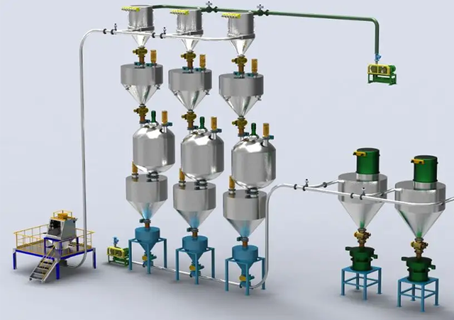
Evaluating feeding mechanisms requires understanding system pressure and material abrasiveness. Rotary airlock valves feed material into dilute phase pressure lines while sealing against the conveying air pressure. If handling abrasive materials, rotary valves require hardened internal coatings, such as tungsten carbide, and tight rotor clearances to prevent rapid wear. Venturi eductors introduce material into a line without moving parts, making them ideal for highly abrasive but low-capacity applications. Pressure vessels, or blow tanks, are mandatory for dense phase systems to introduce material into high-pressure lines without air leakage.
Selecting appropriate tube or pipe schedules depends on system pressure and material wear characteristics. Standard dilute phase systems often use thin-walled aluminum or stainless steel tubing. Dense phase systems require heavier Schedule 40 or Schedule 80 pipe to withstand high internal pressures and the abrasive forces of slow-moving material plugs.
Specifying elbow geometries prevents degradation and wear. Long-radius sweeps allow fragile goods to change direction smoothly, minimizing impact damage. Blind tees or impact elbows force material to impact a trapped pocket of itself, protecting the outer wall of the elbow from abrasive wear. We always specify blind tees for materials like fiberglass or sand.
Sizing filter receivers and cyclone separators requires calculating the specific air-to-cloth ratio. This ratio determines how much air passes through each square foot of filter media. Fine, cohesive dusts require low air-to-cloth ratios (e.g., 3:1) to prevent the filters from blinding. Proper filtration sizing prevents environmental release and protects downstream vacuum pumps or blowers from ingesting destructive dust. You must also calculate the can velocity—the upward speed of air inside the filter housing—to ensure dust actually falls into the hopper rather than remaining suspended around the filter bags.
Even well-designed systems face operational challenges in the field. Anticipating these risks during the engineering phase prevents costly downtime and emergency retrofits.
Designing proper line stepping prevents material from dropping out of suspension. As air travels through a pipeline, pressure drops and the air expands, increasing in velocity. Expanding the pipe diameter at calculated intervals keeps the air velocity consistent. This prevents fragile materials from degrading at the end of long runs and stops heavy materials from settling out and plugging the line.
Utilizing active air injection or booster points in dense phase lines maintains material movement. These air assist valves inject secondary bursts of compressed air along the pipeline route. They break up stubborn material plugs and keep the solid waves moving smoothly, especially after long weekend shutdowns when material may have settled in the pipe.
Multi-product or food-grade systems demand strict cleanability standards. Integrating clean-in-place (CIP) considerations requires specifying sanitary piping connections, highly polished internal finishes, and equipment that disassembles quickly without tools. You cannot use standard threaded pipe fittings in a food-grade system due to the risk of bacterial harborage.
Automated line purging protocols clear the pipeline entirely before switching materials. This prevents cross-contamination between batches, which is critical when handling allergens in food processing or different color pigments in plastics manufacturing. The control system must be programmed to run the blower with the rotary valve off for a specific duration to sweep the line clean.
Theoretical calculations provide a baseline, but they must be validated by empirical material flow testing at a manufacturer's facility. Different batches of the same chemical can behave differently based on moisture content or particle size distribution. Running the actual product through a pilot-scale system confirms the required air velocities, verifies degradation limits, and finalizes the correct flow regime before the equipment is built. Never skip this step when handling a new or proprietary bulk material.
Compile comprehensive material safety data sheets (MSDS) and physical property profiles for every product you intend to convey before contacting equipment vendors.
Define exact peak transfer rates based on batch times and surge requirements, rather than relying solely on daily production averages.
Map out the exact facility routing, counting every vertical lift, horizontal run, and directional change to calculate accurate pressure drops.
Schedule a pilot-scale material flow test with a qualified engineering partner using your actual production material to validate the chosen flow regime.
To ensure seamless implementation and high-performance system design, partnering with an industry-leading specialist is paramount. As an internationally recognized innovator in advanced bulk material handling technologies, Jstark leverages deep engineering expertise, state-of-the-art testing facilities, and high-precision manufacturing to deliver robust, custom-engineered pneumatic systems across global industrial sectors.
A: Dilute phase uses high-velocity, low-pressure air to keep particles fully suspended in the pipeline. It is ideal for light, non-abrasive materials. Dense phase uses low-velocity, high-pressure air to push material in solid plugs or waves. It is designed for heavy, fragile, or highly abrasive materials to minimize wear and degradation.
A: Air requirements are calculated based on the material's bulk density, particle size, and the required transfer rate. Engineers determine the saltation velocity, which is the speed at which particles fall out of the airstream, and add a safety margin. This velocity is multiplied by the pipe's cross-sectional area to determine volumetric airflow.
A: Dilute phase systems typically handle distances up to 600 feet efficiently. Dense phase systems can push materials much further, often exceeding 3,000 feet. This is because dense phase systems utilize higher pressure differentials from compressed air rather than relying on the limited pressure capabilities of standard blowers.
A: Bulk density dictates the required air volume and pipe size. Abrasiveness determines the flow regime and component materials. Highly abrasive powders require low-velocity dense phase conveying and ceramic-lined elbows to prevent rapid equipment failure. Ignoring these properties leads to plugged lines and destroyed piping.
A: Choose a vacuum system when you need to pull material from multiple pick-up points, like several railcars or silos, to a single destination. Vacuum systems are also preferred for handling toxic or highly dusty materials, as any pipeline leaks will draw ambient air in, preventing hazardous dust from escaping.
A: The most effective method is reducing the conveying velocity by utilizing a dense phase system. If using a dilute phase system, implement line stepping by increasing pipe diameter to control air expansion and velocity. Additionally, use specialized fittings like blind tees or long-radius elbows to manage impact zones.
A: NFPA standards require a comprehensive dust hazard analysis. Systems handling combustible dust must incorporate explosion protection strategies. This includes explosion venting panels on filter receivers, chemical suppression systems, and rotary valves designed to act as mechanical isolation devices to prevent deflagration propagation through the pipeline.