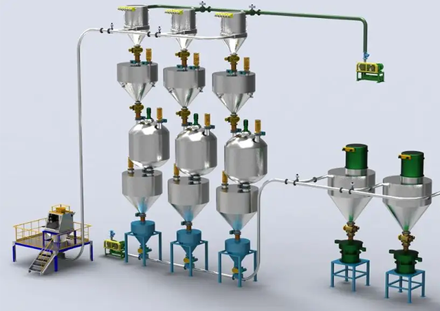
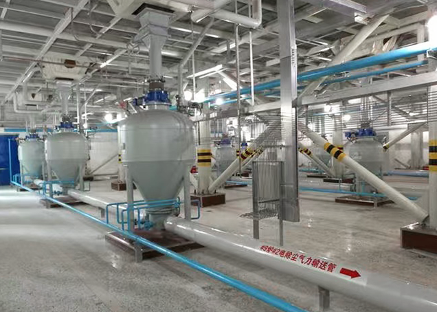
Specifying bulk material handling equipment carries high operational stakes for any industrial facility. Choose the wrong pneumatic system, and you face chronic pipeline plugging, severe equipment wear, and unexpected downtime. Material degradation ruins entire product batches. Energy expenditures skyrocket unnecessarily when blowers are oversized or misapplied. The core engineering challenge lies in matching conveying mechanics to specific material properties. You must account for bulk density, abrasiveness, and heat sensitivity while navigating complex plant layouts. You need a reliable, scalable solution without over-engineering the process. Evaluating vacuum vs pressure conveying requires a strict technical framework. Engineers must look beyond basic throughput requirements. By analyzing routing architecture, hazard containment, and material integrity, you can select a system that maximizes uptime. We will break down the mechanical differences, evaluate core performance dimensions, and outline mitigation strategies for common implementation risks.
Routing dictates the baseline: Vacuum systems excel at drawing material from multiple sources to a single destination, while pressure systems are optimal for pushing material from a single source to multiple delivery points.
Material sensitivity matters: Vacuum conveying inherently avoids transferring blower heat to the material, making it the standard for heat-sensitive or easily degradable compounds.
Safety and containment: Negative pressure (vacuum) systems provide inward leakage, offering superior dust containment for hazardous, toxic, or highly regulated materials.
Distance and capacity scaling: Positive pressure systems support significantly higher pressure differentials, allowing for longer conveying distances and higher throughput capacities compared to vacuum limits.
Economic tipping points: As capacity and distance scale up, pressure systems become significantly more economical and energy-efficient than vacuum systems.
Table of Contents
Mechanical flow in a push system relies on a rotary positive displacement blower or a dedicated air compressor. This equipment introduces compressed air at the system inlet. The high-velocity air captures the bulk material and pushes it through the pipeline toward its destination. The air and material mixture travels under positive pressure until it reaches the discharge point. Engineers typically specify Roots-type blowers for these applications due to their ability to deliver consistent air volumes against varying line pressures.
The standard component stack requires precise engineering to maintain system equilibrium. It starts with the air source, an inlet filter, and an inline discharge silencer. A rotary airlock valve or a pressurized blow tank meters bulk material directly into the moving airstream. The conveying line transports the mixture across the facility, utilizing long-radius sweeps to minimize pipe wear. Inline diverter valves route the product to specific silos or processing lines. Finally, a terminal filter receiver or a simple bin vent separates the conveying air from the bulk material at the end of the run.
Operating pressure ranges vary significantly based on the chosen conveying phase. Dilute phase systems typically operate up to 15 psig, keeping material fully suspended in the airstream at high velocities. Dense phase systems utilize much higher pressures, often exceeding 40 to 60 psig. This high pressure pushes heavy, abrasive, or fragile loads at lower velocities, moving the material in distinct slugs rather than a continuous suspended cloud.
A vacuum pump or positive displacement exhauster sits at the delivery end of the line, driving the mechanical flow. This device creates negative pressure throughout the entire piping network. The system pulls ambient air and bulk material into the pipeline from the source. The material rides the vacuum stream until it reaches the destination receiver. Liquid ring pumps or rotary claw exhausters are common choices for generating the necessary vacuum levels.
The component stack looks entirely different from a pressure setup. It begins with a pickup wand, a bag dump station, or a simple suction adapter at the material source. The conveying line routes the material directly to a vacuum receiver. This receiver includes integrated pulse-jet filtration to separate the dust from the air before the air reaches the pump. The vacuum producer sits downstream of this filter, heavily protected from any accidental material ingress.
Negative pressure operates under strict physical limitations. The maximum theoretical vacuum is -14.7 psig at sea level. Practical industrial limits hover around -12 psig. This absolute ceiling directly limits maximum conveying distances and overall throughput capacities. You simply cannot generate more pulling force once you approach absolute vacuum. Pushing a vacuum system past -12 psig causes the air to expand rapidly, creating massive velocity spikes that degrade the material and blind the filter media.
Hybrid systems combine both methods to handle complex material transfer requirements. A vacuum system pulls material from a difficult source where space is restricted. Railcar unloading often requires this approach. The vacuum pulls product from the railcar hopper into an intermediate transfer receiver. This receiver then drops the material through a heavy-duty rotary valve into a positive pressure system. The pressure side pushes the material to distant storage silos across the plant.
This configuration solves highly specific logistical problems. Source accessibility often remains limited in older facilities. You cannot easily fit heavy blowers, acoustic enclosures, and rotary valves underneath a railcar or a low-clearance bulk bag discharger. At the same time, the final destination requires long-distance, high-capacity transfer that a standalone vacuum system cannot achieve. The pull-push setup bridges this gap, leveraging the flexible pickup of vacuum and the long-haul power of positive pressure.
Evaluate the multiple-to-one scenario carefully. Vacuum systems dominate this layout. They efficiently pull material from multiple silos, railcars, or bulk bags. The lines converge into a single mixer, scale hopper, or receiver. You only need one vacuum producer at the destination, simplifying the equipment footprint and reducing maintenance points. A commercial bakery pulling flour from three outdoor silos into a single indoor dough mixer represents the perfect vacuum application.
Evaluate the one-to-multiple scenario next. Pressure systems handle this requirement perfectly. You distribute material from a single silo to multiple extruders, packaging lines, or storage bins. Inline diverter valves direct the flow to the active destination. One blower at the source pushes material anywhere in the plant, making it highly efficient for distribution networks. A plastics facility pushing polyethylene pellets from one railcar to six different storage silos relies entirely on positive pressure.
Pickup point flexibility sets the two technologies apart. Vacuum systems allow for mobile, unmetered, or temporary pickup points. Operators frequently use hand-held wands to empty drums or sweep up spills. Pressure systems demand fixed, mechanically metered feed points. You must install a precision rotary airlock valve at every single pressure inlet to prevent conveying air from blowing backward into the material source.
Thermal dynamics play a massive role in system selection. Positive pressure blowers generate significant heat of compression. A standard rule of thumb dictates a 15-degree Fahrenheit temperature rise for every 1 psi of operating pressure. A system running at 10 psig adds 150 degrees to the ambient air. This heat transfers directly into the conveying air. Hot air melts heat-sensitive plastics, causing long streamers known as angel hair to form inside the pipeline. It degrades food ingredients and alters pharmaceutical compounds. Vacuum systems pull ambient air, keeping materials cool during transit.
Friability dictates velocity control. Material velocity impacts fragile particles heavily. High speeds cause severe particle attrition, generating unwanted dust and altering product bulk density. System pressure choices influence terminal velocity. Pressure systems often require stepped line sizes to manage expanding air and maintain gentle velocities over long distances. Vacuum systems naturally expand air toward the end of the line, requiring careful receiver design and tangential inlets to prevent high-speed particle impact against the vessel walls.
Pressure systems offer massive scalability for long-haul conveying. Facilities routinely push material across hundreds of feet, navigating complex pipe racks and elevation changes. High-tonnage bulk transfer relies entirely on positive pressure. The available energy is limited only by the compressor's horsepower rating and the pipeline's structural pressure ratings. Systems moving 100,000 pounds per hour over 1,000 feet are common in the cement and mining industries.
Vacuum systems face strict distance and capacity ceilings. You cannot overcome the absolute limits of atmospheric pressure. Once you reach -12 psig, you have exhausted your pulling power. Vacuum works best for short to medium distances, typically under 250 feet, with moderate throughput requirements under 20,000 pounds per hour. Pushing beyond these limits results in line stalling, frequent plugging, and excessive wear on the vacuum pump.
Dilute phase pressure conveying keeps non-abrasive materials in continuous suspension. Dilute phase vacuum conveying does the exact same thing using negative pressure. Both rely on high air velocities, generally between 3,000 and 5,000 feet per minute, to prevent material fallout. They are ideal for flour, sugar, plastic pellets, and other robust, lightweight powders that do not degrade easily upon impact.
Dense phase conveying becomes necessary for highly abrasive or fragile materials. This method uses low velocity, often under 1,000 feet per minute, and high pressure to push dense slugs of material through the pipe. Dense phase is predominantly a positive pressure application because it requires significant force to move the heavy material slugs. Vacuum dense phase exists, but engineers restrict it to very specific, short-distance applications where material degradation is the primary concern and space constraints prohibit pressure vessels.
System Architecture and Capacity Comparison
Evaluation Feature | Positive Pressure (Push) | Negative Pressure (Vacuum) |
|---|---|---|
Optimal Routing | One source to multiple destinations | Multiple sources to one destination |
Distance Capability | High (Hundreds to thousands of feet) | Low to Medium (Limited by atmosphere) |
Material Heat Risk | High (Blower heat of compression) | Low (Draws ambient cooling air) |
Feed Point Requirement | Fixed, metered (Rotary airlock) | Flexible, mobile (Wands, simple nozzles) |
Leakage Behavior | Outward (Dust escapes into plant) | Inward (Air draws into pipe) |
Typical Max Pressure | 15 psig (Dilute) / 60+ psig (Dense) | -12 psig (Absolute practical limit) |
Pressure systems carry a severe risk of outward leaks. Worn pipe joints, failing rotary valve seals, or degraded flex hoses allow material to escape into the plant environment. This poses extreme hazards when handling toxic chemicals or active pharmaceutical ingredients. Combustible dust creates explosive environments if it accumulates on rafters or equipment surfaces. Biologically active materials require strict containment to protect operators from exposure.
Vacuum systems mitigate these risks entirely. Any pipe leak draws ambient air inward. The material stays securely inside the pipe. This prevents environmental contamination. It heavily aids in meeting strict NFPA 652 and ATEX compliance standards for hazardous dust management. Plant safety managers strongly prefer vacuum systems when handling highly regulated powders, as the inherent mechanical design acts as a fail-safe against fugitive dust emissions.
Pressure systems introduce specific contamination risks. Standard positive displacement blowers can introduce oil or moisture into the airstream. Food or pharma applications require sanitary, oil-free compressors. You must often install inline desiccant air dryers and aftercoolers to prevent material clumping. If compressed air cools in the pipeline, condensation forms, turning powders like cement or flour into solid blocks inside the pipe.
Vacuum systems face ambient environmental risks. Vacuum pulls ambient plant air directly into the pipeline at the pickup point. Highly hygroscopic materials, such as whey powder or specialized resins, absorb this moisture instantly. You must install HVAC conditioning or dry-air blanketing at the pickup point to protect sensitive powders. Failing to control ambient humidity leads to sticky buildup inside the vacuum receiver and rapid blinding of the filter media.
Plug behavior contrasts sharply between the two systems. Pressure systems pack material tightly into a severe plug if the line backs up. The blower keeps pushing until the pressure relief valve trips. This creates a solid pipe blockage requiring extensive manual cleanout. Operators must dismantle pipe sections, hammer the exterior, or use high-pressure air lances to clear the packed material, resulting in hours of lost production.
Vacuum systems naturally limit packing force. When a plug forms, airflow stops. Without airflow, the vacuum drops and pulling force ceases entirely. The material rests loosely in the pipe rather than packing into a solid brick. Line cleanout becomes much easier. Operators can often clear the line simply by pulsing the filter receiver or opening a cleanout port to reintroduce airflow. This reduces downtime and lowers the risk of catastrophic pipe damage.
Pressure systems face inherent risks at the feed point. Conveying air naturally seeks the path of least resistance. It escapes upward through the rotary airlock clearances. This blow-by air hits the incoming material in the shear zone. It causes bridging in the hopper, fluidizes light powders, and blocks material feed entirely. If the blow-by is severe enough, the system starves for material, dropping throughput drastically.
Engineers use specific mitigation tactics to combat blow-by. Venting hoppers redirect the escaping air away from the product flow, routing it to a separate dust collector. Specifying tighter valve clearances reduces the leakage volume, though this increases the risk of rotor binding with abrasive materials. Alternatively, utilizing vacuum pickup eliminates blow-by entirely, as air flows in the exact same direction as the material entering the system.
Installation realities often dictate system choice. Vacuum receivers require significant headroom above the destination equipment. You must fit the filter receiver housing, the conical hopper, the discharge valve, and any transition pieces directly above mixers or packaging machines. Facilities with low ceilings struggle to accommodate vacuum destinations without expensive roof modifications or structural steel additions.
Pressure systems require less complex terminal equipment. A simple bin vent filter often suffices at the destination silo, requiring minimal headroom. However, they demand robust structural support at the source. Heavy blower packages require large footprints on the plant floor. Acoustic enclosures take up valuable space near the material feed point. You must map your facility's physical constraints, measuring exact vertical clearances, before selecting a system architecture.
Material Suitability Matrix
Material Type | Recommended System | Engineering Rationale |
|---|---|---|
Titanium Dioxide (TiO2) | Vacuum | Highly cohesive; vacuum prevents packing in the line during a stall. |
Plastic Pellets (PE/PP) | Pressure | High throughput over long distances; requires aftercoolers to prevent melting. |
Active Pharma Ingredients | Vacuum | Strict containment required; inward leakage prevents operator exposure. |
Portland Cement | Pressure (Dense Phase) | Highly abrasive and heavy; requires high pressure to move at low velocities. |
Granulated Sugar | Vacuum or Pressure | Depends on routing; requires strict velocity control to prevent shattering. |
Take these actionable next steps to finalize your system design:
Map all plant routing constraints, measuring exact vertical and horizontal distances to determine feasibility.
Conduct pilot-scale material testing with a systems integrator to validate flow rates and terminal velocities.
Calculate exact air-to-cloth ratios required for your specific dust load to prevent filter blinding.
Verify facility headroom above all destination mixers and storage silos to ensure equipment fits.
Audit your plant's ambient humidity levels to determine if dry-air blanketing is required at the pickup points.
Backed by decades of deep engineering expertise and advanced manufacturing, leading providers like Jstark engineer fully customized pneumatic conveying systems tailored to your exact facility layout, eliminating downtime and optimizing your bulk material throughput.
A: The primary difference lies in the air mover's location and mechanics. Pressure systems use a blower at the inlet to push material through the line. Vacuum systems place an exhauster at the destination to pull material and ambient air into the pipeline.
A: Vacuum systems are ideal for heat-sensitive materials because they avoid blower heat. They are also the standard for hazardous dust, as inward leaks prevent contamination. Use them when you need mobile pickup points or have a multiple-source-to-one-destination layout.
A: Yes. Combination pull-push systems are highly effective. A vacuum side pulls material from difficult access points, like railcars. The material drops into a transfer receiver, which then feeds a positive pressure system to push the bulk material to distant silos.
A: Dense phase conveying is generally better for fragile materials because it moves product at low velocities, reducing particle attrition. While dense phase is typically a pressure system, vacuum systems can also handle fragile materials gently if designed with precise velocity control.
A: Vacuum systems are limited by atmospheric pressure, restricting them to shorter distances and lower capacities. Positive pressure systems offer immense scalability. You can increase compressor size to push heavy bulk materials across hundreds of feet efficiently.