Poorly specified bulk material handling systems carry severe operational penalties for processing facilities. Mismatching the conveying method to the material causes chronic pipeline plugging, rapid material degradation, and excessive downtime. Maintenance crews spend hours dismantling blocked pipe sections while production lines stop completely. The core engineering challenge lies in accurately aligning pneumatic dynamics with specific material behaviors, facility layouts, and strict compliance mandates. Selecting the wrong pressure dynamic directly leads to hazardous dust exposure, compromised product integrity, and accelerated system wear. To avoid these mechanical failures, operators must conduct a rigorous technical evaluation of positive vs negative pressure conveying. This assessment establishes the foundation for a reliable system based on capacity limits, transfer distances, and distinct material characteristics. Understanding the fundamental physics behind these systems ensures the chosen equipment handles the product efficiently without compromising safety or throughput.
Fundamental Difference: Positive pressure systems "push" materials using blowers/compressors (ideal for long distances and high capacities), while negative pressure (vacuum) systems "pull" materials (ideal for dust containment and short-to-medium distances).
Routing Optimization: Negative pressure excels at routing from multiple pickup points to a single destination; positive pressure is superior for moving material from a single source to multiple discharge points.
Safety and Compliance: Vacuum conveying inherently prevents outward dust leakage, making it the standard for hazardous, toxic, or combustible materials requiring strict NFPA/OSHA compliance.
Material Integrity: Negative pressure typically operates at lower pressure differentials and generates less heat, offering gentler handling for friable powders or heat-sensitive granules compared to positive pressure systems.
Table of Contents
Pneumatic conveying relies on fluid dynamics to move bulk solids through enclosed pipelines. You utilize specific air velocities and pressure differentials to overcome gravity and pipeline friction. The moving air stream either fully suspends the particles or pushes them along the bottom of the pipe. We categorize this movement into distinct phases based on the air-to-material ratio and the velocity of the gas.
Dilute phase conveying uses high-velocity air to keep particles fully suspended in the air stream. It operates at lower pressures but requires air speeds often exceeding 3,000 to 5,000 feet per minute to maintain the saltation velocity—the minimum speed required to keep particles from falling out of suspension. Dense phase conveying uses low-velocity air to push material in heavy slugs or continuous plugs. This method requires much higher pressure differentials but operates at speeds as low as 500 feet per minute, which protects fragile materials from high-speed impacts.
These pressure dynamics apply differently across various conveying phases and require precise mechanical control. Operators regulate airflow velocity using variable frequency drives connected to the blowers. You can also implement stepped piping designs that expand the pipe diameter to maintain constant air velocity as pressure drops over long distances. Precise airflow control allows facilities to smoothly transfer products. Maintaining the correct velocity prevents particles from dropping out of suspension. This avoids pipeline plugging while keeping speeds low enough to prevent mechanical damage upon impact with pipe elbows.
The primary distinction between pneumatic systems comes down to where you apply the air motive force relative to the material entry point. Positive pressure systems introduce compressed air upstream of the material feed. This configuration creates a higher-than-atmospheric pressure environment inside the pipeline. The pressurized air forcefully pushes the material downstream toward its destination. The energy concentrates at the beginning of the line and dissipates as the material travels through the piping network.
Negative pressure operates on the exact opposite principle. The system evacuates air downstream of the material delivery point, typically at the very end of the line. This mechanical evacuation creates a lower-than-atmospheric pressure environment inside the pipe. Atmospheric pressure at the pickup point then rushes in to fill the void. This rushing air draws the bulk material through the line. The motive force relies entirely on the pressure differential between the ambient air and the vacuum created by the pump.
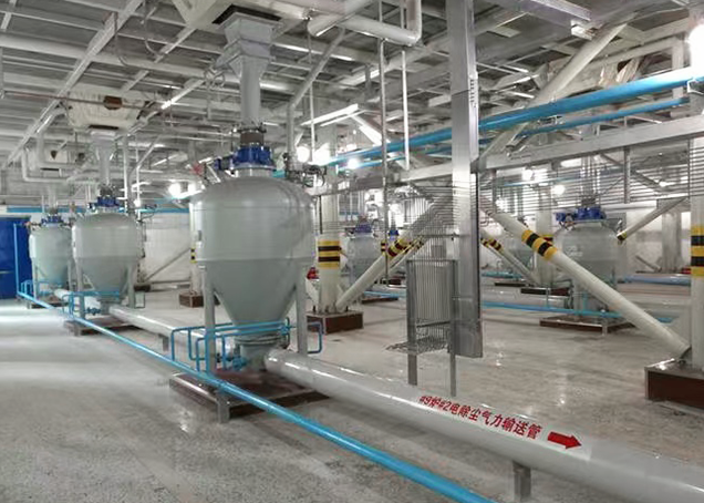
Positive pressure systems rely on a heavy-duty equipment stack to generate and maintain the necessary conveying force. The standard setup begins with the air source. You typically use positive displacement blowers for dilute phase or high-pressure air compressors for dense phase applications.
A standard positive pressure layout includes several specific components:
Positive displacement blower or compressor package equipped with intake filters and silencers.
Rotary airlock valve or blow-through adapter to feed material into the pressurized line.
Heavy-schedule conveying pipeline designed to withstand high internal pressures.
Pressurized diverter valves for routing material to various destinations.
Terminal filter receiver or bin vent at the destination to separate the air from the product.
The rotary airlock valve plays a highly critical role in this architecture. It must introduce bulk material from a hopper at atmospheric pressure into a highly pressurized conveying line while maintaining a strict air seal. The valve utilizes a rotating rotor with precision-machined pockets. As the rotor turns, it drops material into the line. The tight clearances between the rotor blades and the housing—often machined to tolerances of 0.004 to 0.006 inches—prevent the conveying air from escaping upward. Without a properly functioning rotary valve, the system rapidly loses pressure, conveying efficiency drops, and material flow ceases entirely.
These systems excel at handling high capacities over extremely long distances. Positive displacement blowers and compressors achieve massive pressure differentials. Dense phase systems can reach operating pressures up to 45 psig. Dilute phase systems typically operate up to 15 psig. This high pressure provides the sheer mechanical force necessary to transfer heavy aggregates, dense plastic resin pellets, and massive material volumes over thousands of feet of piping. We routinely see positive pressure lines moving over 100,000 pounds of material per hour across large manufacturing campuses.
Positive pressure also drastically simplifies single-to-multiple routing topography. When a facility needs to move material from one main storage silo to several different processing lines, positive pressure works best. Pressurized diverter valves installed along the pipeline instantly redirect the moving material stream. A single blower can push material to a dozen different receiving bins simply by actuating the correct sequence of diverter valves from the central control panel.
Pressurized pipelines carry inherent mechanical and environmental risks. Outward dust leakage at pipe joints, access ports, or worn valves poses a serious hazard. If the pipeline handles toxic chemicals or combustible dust, any outward leak immediately threatens worker safety and facility compliance. Maintenance teams must constantly monitor flange gaskets and coupling seals to ensure the pressurized air does not force hazardous material into the plant environment.
Component wear introduces another significant limitation. Blow-by air inevitably escapes upward through the clearances of the rotary airlock. This upward blast of air impedes material flow from the feed hopper, causing bridging or ratholing. It also accelerates component wear when handling highly abrasive materials like alumina or silica sand. The escaping air acts like a sandblaster against the valve housing, destroying the tight tolerances required for a proper seal.
The physical act of compressing air generates significant thermal energy. The air exiting a positive displacement blower gets exceedingly hot, sometimes exceeding 250 degrees Fahrenheit. This heat transfers directly to the material being conveyed. For heat-sensitive materials like specific plastic resin pellets, waxes, or food powders, this thermal energy causes the product to melt, smear, or form angel hair inside the pipe. Facilities handling these materials must integrate specialized air coolers and heat exchangers downstream of the blower to mitigate this thermal risk.
Vacuum systems pull material using a fundamentally different equipment configuration. The air mover sits at the very end of the conveying line. You typically use a positive displacement vacuum pump or a regenerative exhauster depending on the required vacuum level and airflow volume.
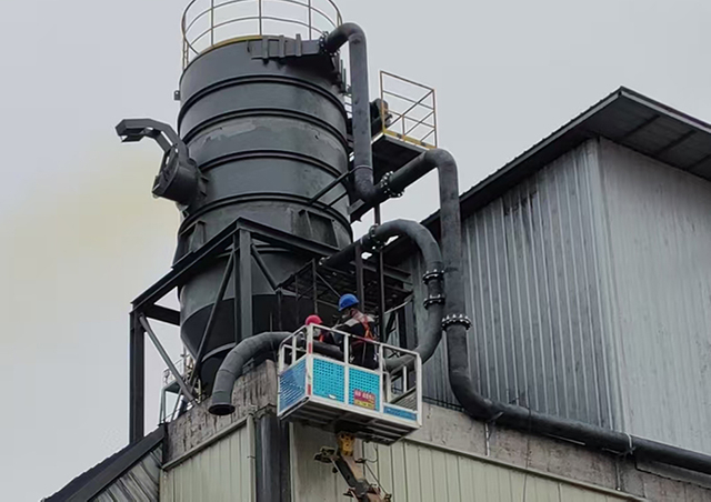
Operators use pickup wands, simple rotary valves, or suction boxes to introduce material into the airflow. The material travels through the conveying lines directly into highly efficient filter receivers. The filter receiver must completely separate the bulk product from the air stream before that air reaches the vacuum pump. If dust bypasses the filter, it will cause catastrophic damage to the pump's internal lobes or impellers, leading to immediate mechanical failure.
Vacuum conveying provides unmatched dust containment and facility cleanliness. The inward-pulling vacuum ensures that if a pinhole leak develops in the pipeline, ambient air draws into the system. The system never blows fugitive dust out into the facility environment. This strict containment makes vacuum systems the absolute standard for cleanrooms, pharmaceutical processing, and the handling of highly hazardous chemicals where operator exposure limits are strictly regulated.
Negative pressure streamlines multiple-to-single routing operations. Facilities can efficiently draw materials from multiple disparate sources into a single processing vessel. You can pull from railcars, bulk bags, supersacks, and manual bag dump stations using a single vacuum receiver. This eliminates the need for multiple blowers and complex diverter valve networks at the source.
These systems also offer exceptionally gentle handling. The lack of rotary airlock valves at the pickup point protects materials from mechanical shearing. Vacuum pumps do not introduce compressed heat into the material stream at the pickup point. The lower operating temperatures protect friable powders and heat-sensitive granules from thermal degradation, ensuring the product arrives at its destination in its original state.
Atmospheric pressure dictates the absolute physical limits of vacuum systems. The maximum theoretical vacuum at sea level is roughly 14.7 psi. The practical operational limit is much lower, typically around 10 to 12 inches of mercury (roughly 5 to 6 psi). This physical constraint restricts vacuum systems to shorter transfer distances, generally under 300 feet. Throughput capacities also remain significantly lower compared to highly pressurized lines. You simply cannot pull heavy materials over long distances with the limited pressure differential available from the atmosphere.
System efficiency relies entirely on the performance of the terminal filter receiver. Vacuum systems require significantly larger filter surface areas than positive pressure systems. As air pulls under vacuum, its volume expands. This expanded volume of air demands extra filtration capacity to maintain the correct air-to-cloth ratio. If the filter media blinds or clogs with fine dust, the pressure drop across the filter spikes. Vacuum pulling performance degrades immediately. Rigorous pulse-jet cleaning mechanisms are required to keep the filters clear and maintain system throughput.
Material properties dictate the required conveying method more than any other variable. Heavy aggregates like sand, gravel, and cement require the brute force of positive pressure to remain suspended or move in dense plugs. Fine, lightweight powders like baking flour, carbon black, and pharmaceutical active ingredients handle easily under the gentler pull of a vacuum.
Cohesive, fluidizable powders like titanium dioxide often pack together tightly when subjected to positive pressure. This packing causes severe pipeline blockages that require manual dismantling to clear. Vacuum systems naturally aerate these powders, preventing packing and maintaining flowability. Conversely, free-flowing granules and durable plastic pellets push easily via positive pressure without issue.
Abrasiveness and friability heavily influence component wear rates and system selection. Highly abrasive materials quickly destroy the tight clearances of positive pressure rotary valves. This leads to massive blow-by leaks and system failure. Friable materials that easily crumble or shatter, such as roasted coffee beans or fragile cereals, degrade rapidly when forced through pressurized diverters or sheared by rotary valve blades. Vacuum systems eliminate the need for these aggressive feeding mechanisms, preserving the integrity of friable products.
Routing geometry provides a clear, actionable decision matrix for system selection. When a facility requires multiple pickup points feeding a single discharge point, negative pressure is the optimal engineering choice. A single vacuum receiver can pull from a dozen different silos sequentially without needing complex valving at every source.
When the layout demands a single pickup point feeding multiple discharge points, positive pressure is vastly superior. A single blower pushes material through a network of diverter valves to fill an entire row of storage silos. This minimizes the amount of equipment required at the destination points.
Vertical lift requirements and footprint constraints also dictate system design. Positive pressure requires placing large blowers, acoustic enclosures, and air coolers at the start of the line. This often requires significant floor space near the material intake. Vacuum systems require placing heavy vacuum pumps and oversized, towering filter receivers at the end of the line. This often means reinforcing the roof or structural steel above the final destination vessel to support the massive weight of the receiver and the accumulated material.
Theoretical engineering calculations often meet harsh real-world variables on the plant floor. Ambient humidity heavily impacts powder flowability and filter blinding. High humidity drawn into a vacuum system causes hygroscopic powders like sugar or salt to clump. This instantly blinds the filter receiver media and shuts down the process. Facilities operating in humid environments must condition the intake air to prevent this failure.
Plant altitude directly affects atmospheric pressure, which alters vacuum efficiency. A manufacturing plant operating at high altitude in Denver has significantly less atmospheric pressure to utilize than a plant at sea level. High-altitude facilities lose significant vacuum pulling power and require oversized pumps and larger conveying lines to achieve the same throughput.
Complex pipeline routing with excessive elbows creates massive friction drops. Every 90-degree sweep elbow adds equivalent feet of straight pipe resistance to the system. These practical variables heavily impact the technical evaluation of positive vs negative pressure conveying. Engineers must upsize blowers or switch dynamics entirely to overcome layout constraints and friction losses.
Safety compliance drives many pneumatic conveying decisions in modern manufacturing. OSHA and the NFPA enforce strict combustible dust regulations across all industries handling bulk solids. Negative pressure serves as the default standard for mitigating explosive dust environments.
The inward airflow prevents fugitive dust emissions from settling on factory rafters and equipment. This strict containment helps facilities meet indoor air quality mandates and pass safety inspections. Most importantly, it eliminates the dispersed fuel source required for secondary dust explosions. If a positive pressure line ruptures, it creates an immediate dust cloud hazard. If a vacuum line ruptures, it simply sucks air into the pipe until the system shuts down.
Operational Comparison Matrix
Technical Feature | Positive Pressure Systems | Negative Pressure (Vacuum) Systems |
|---|---|---|
Primary Motive Action | Pushes material downstream | Pulls material upstream |
Optimal Routing Geometry | Single source to multiple destinations | Multiple sources to single destination |
Distance & Capacity Limits | Long distances, exceptionally high capacity | Short distances, low-to-medium capacity |
Dust Containment Profile | High risk of outward dust leakage | Inward leakage only (highly contained) |
Ideal Material Suitability | Heavy aggregates, durable plastic pellets | Friable powders, hazardous/toxic dust |
Equipment Footprint | Heavy equipment at material source | Heavy equipment at material destination |
Certain complex industrial applications require both dynamics in a single continuous process. A pull-push system combines vacuum and pressure to solve specific logistical challenges that neither system handles alone.
For example, a facility might need to unload a bulk railcar but cannot dig a deep mechanical pit beneath the tracks for a positive pressure rotary valve. Instead, the facility uses a vacuum wand or a specialized track pan to draw the material up and out of the railcar. The vacuum pulls the material into an intermediate transfer vessel located nearby.
This transfer vessel acts as a pressure boundary. It features a filter receiver on top to separate the vacuum air, and a heavy-duty rotary airlock on the bottom. As the material drops through the airlock, a high-capacity positive pressure blower pushes the material thousands of feet to distant storage silos.
Synchronizing a hybrid system requires advanced engineering and precise instrumentation. The control system must perfectly balance the vacuum intake rate with the pressure discharge rate. This synchronization ensures seamless material transfer without creating bottlenecks. If the vacuum pulls faster than the blower pushes, the intermediate vessel overfills. If the blower pushes faster than the vacuum pulls, the downstream pressurized line starves and wastes energy.
Conduct pilot-scale material testing to accurately determine the bulk density, flowability, moisture sensitivity, and degradation rates of your specific product before sizing any equipment.
Map your facility layout to identify the exact number of pickup and discharge points, calculating all vertical lifts and 90-degree elbows to determine total pipeline friction loss.
Audit your material safety data sheets against NFPA combustible dust standards to determine if inward-pulling vacuum containment is legally required for your process environment.
Consult with a dedicated pneumatic conveying engineer to validate your pipeline routing and calculate necessary altitude adjustments for your specific geographic location.
To ensure long-term efficiency and tailored system designs, industry-leading manufacturers like Jstark deliver cutting-edge engineering expertise and customized pneumatic solutions built to handle the most demanding material processing challenges safely and reliably.
A: Yes. Pull-push hybrid systems combine both methods to solve complex routing issues. Facilities often use vacuum to unload railcars without digging deep pits, draw the material into an intermediate transfer vessel, and then use a positive pressure blower to push the material to distant storage silos.
A: Negative pressure vacuum systems are the safest choice for combustible dust. The inward-pulling airflow ensures that any pipeline leaks draw ambient air in, preventing hazardous dust from escaping into the facility. This containment aids significantly in strict NFPA and OSHA compliance.
A: Vacuum systems are physically limited by atmospheric pressure. While theoretical limits exist, practical industrial applications generally cap negative pressure conveying distances at around 200 to 300 feet. The exact limit depends heavily on the material's bulk density and pipeline routing complexity.
A: Positive pressure utilizes rotary airlock valves that mechanically shear particles. The air compressors also generate significant heat, which melts heat-sensitive materials. Additionally, the higher air velocities required cause friable materials to shatter upon impact with pipe elbows.
A: Heavier bulk densities require greater mechanical force to move through a pipeline. Positive pressure blowers generate the high pressure differentials necessary to push heavy aggregates. Vacuum systems lack the physical pulling force to efficiently move highly dense materials over long distances.
A: Generally, no. Heavy aggregates like sand, gravel, or cement require high pressure differentials to remain suspended or move through the pipeline. Vacuum systems cannot generate enough pulling force to move these heavy materials efficiently, making positive pressure the required choice.